Imagine you’re in a dark room with a friend and a flashlight. You agree on a simple code: one short flash means “0”, one long flash means “1”. You can now send binary messages just by pressing the flashlight button.
LiFi is the grown‑up, insanely fast, highly engineered version of this game:
turning internet data into tiny, invisible flickers of light from an LED, and back.
Wi‑Fi vs LiFi: different carriers, same idea
At the protocol level, LiFi can still move IP packets, HTTP traffic, etc. The big difference is the physical layer:
- Wi‑Fi: uses radio waves (2.4/5 GHz), antennas, RF power amplifiers, mixers.
- LiFi: uses visible/infrared light, LED lamps as transmitters, photodiodes as receivers.
So LiFi is essentially wireless optical communication in the room air, instead of in a fiber.
Key consequences of using light instead of RF:
- Light does not go through walls → better spatial confinement and privacy.
- No RF interference → attractive for hospitals, aircraft, industrial sites.
- You need line‑of‑sight or at least reflected light → coverage is more like a spotlight than a Wi‑Fi bubble.
Inside the LiFi lamp: how data rides on brightness
Modern LEDs can switch on and off much faster than human eyes can notice – typically in the MHz range. Human vision fuses anything above ~60 Hz into continuous light, so LiFi can hide data in brightness changes without visible flicker.
A simplified LiFi transmitter chain looks like this:
- Data (e.g., Ethernet frames) enters a LiFi controller.
- The controller encodes this into a stream of bits.
- A modulator converts bits into a varying drive current.
- The LED driver pushes that current through the LED array.
- The LED’s light intensity now carries the data.
The simplest scheme is On‑Off Keying (OOK):
- logical
1→ LED slightly brighter, - logical
0→ LED slightly dimmer.
In practice you don’t turn the lamp fully off and on; you dither around a base brightness level, so the room lighting stays constant while a fast variation rides on top.
More advanced LiFi uses schemes like OFDM, multi‑level amplitude modulation, or PWM with varying duty cycles to squeeze more bits per symbol and improve robustness.
The receiver: from photons back to packets
On the other side, a photodiode plays the role of an ultra‑fast light sensor. It outputs a current proportional to incident light power:
- more light → more photocurrent,
- less light → less photocurrent.
The analog front‑end typically does this:
- A transimpedance amplifier (TIA) converts the tiny photocurrent into a voltage.
- Filters remove DC (ambient light) and low‑frequency noise.
- An ADC or comparator digitizes the signal.
- A demodulator reconstructs the bit stream from the waveform.
- Higher layers reassemble frames and pass them to Ethernet/USB/UART, then to the OS network stack.
For basic OOK, demodulation can be as simple as comparing the signal to a threshold: above → 1, below → 0. Real systems add clock recovery, equalization, and error correction to handle reflections, dimming changes and noise.
Multi‑level and multi‑color: more bits per flash
LEDs are not limited to just “on” and “off”. You can drive them at many distinct brightness levels, which means each symbol can carry multiple bits.
Example with 4 levels:
- level 0 →
00 - level 1 →
01 - level 2 →
10 - level 3 →
11
That’s 2 bits per symbol instead of 1. Combine this with high symbol rates and you already reach megabit speeds.
If you have an RGB LED fixture, each color channel (R, G, B) can be modulated independently, effectively giving you three parallel LiFi channels in the same physical lamp. The receiver can separate them using color filters or multi‑channel photodiodes.
Real‑world limitations
LiFi is powerful but not magic. The physics of light imposes some hard constraints:
- Needs line‑of‑sight or strong reflections; block the lamp, lose the link.
- Sunlight and other lamps create optical noise; receivers need good filtering.
- When the light is fully off, the classic LiFi channel is gone (some systems add an invisible infrared component to keep data alive in “off” mode).
- Every client needs an optical front‑end (photodiode, lens, amplifier), which is not yet built into most laptops/phones.
In return you get:
- No RF emissions in sensitive environments.
- Natural spatial security: the link stays mostly inside the lit area.
- The possibility to reuse lighting infrastructure for data.
Bench‑top “LiFi‑like” experiment for makers
Full‑blown LiFi is complex, but you can easily build a low‑speed optical link to understand the principles.
Transmitter (e.g., Arduino):
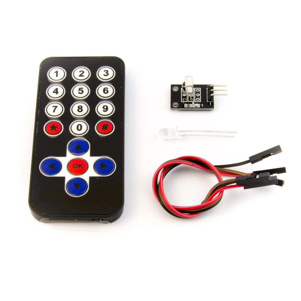
- Drive a high‑power white or IR LED with a transistor from a digital pin.
- Encode serial data as OOK: for each bit, LED on for
1, off for0. - Start with very low speeds (e.g., 1 kbit/s) and increase gradually.
Receiver:
- Use a photodiode + TIA (an op‑amp in transimpedance configuration).
- Feed the output to an
analogReadpin or to a comparator. - In firmware, sample at a fixed rate, detect edges/levels, and decode into bytes (a simple UART‑like framing works well).
Put the LED and photodiode a meter apart, shield them from room light with tubes, and you’ll have your own mini LiFi demo.
Practical tips for projects
- Control the spectrum. If possible, use an IR LED and an IR photodiode with a matching band‑pass filter. This drastically reduces interference from room lighting and screens.
- Drive LEDs properly. Never pull a high‑power LED directly from a microcontroller pin. Use a MOSFET or BJT, a current‑limiting resistor or constant‑current driver, and keep wiring short to avoid ringing.
- Stabilize timing. Use hardware timers or carefully written interrupt code for symbol timing, not
delay(). Accurate timing makes clock recovery and decoding much easier and reliably boosts your maximum data rate.